


Key Features
- Voltage-Controlled Clock Multiplier With CV Or Manual Control
- CV Control Combined With Mode Switch Determines Multiplication
- Manual Control Can Be Used Instead Of External CV Signal
- Ability To Generate Ratcheting Sequences For Multiple Gate Pulses
- Nine LEDs Are Used To Display Active Multiplication Factor
Doepfer A-160-5 Clock Multiplier/Ratcheting Controller (4HP) Overview
Product Ref: 96804
Full Description
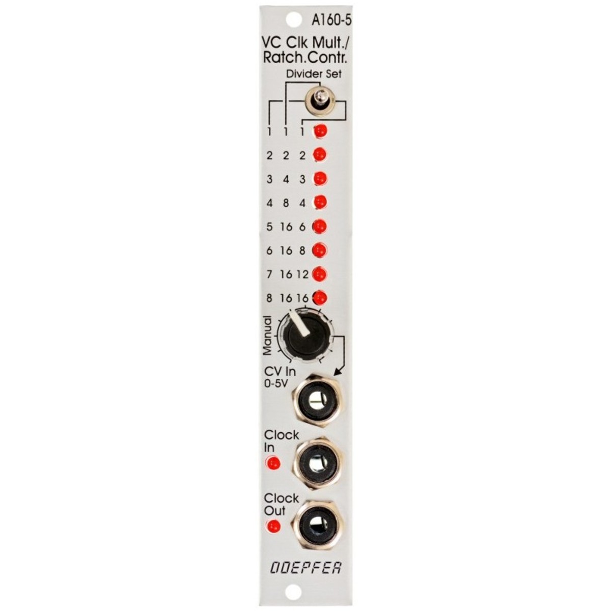
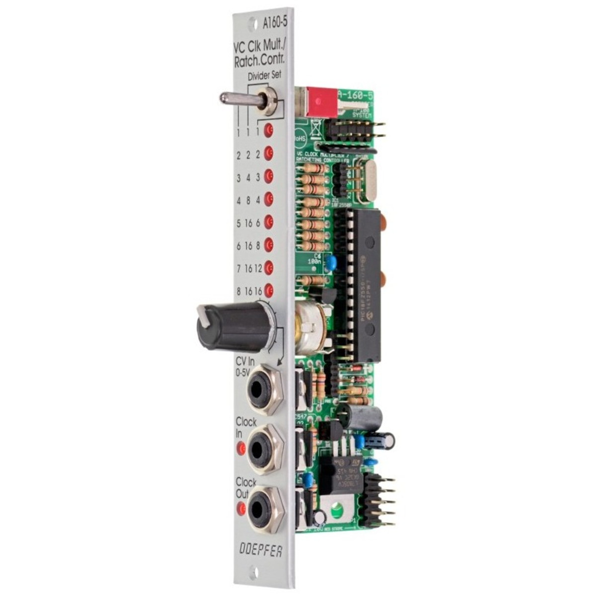
View Full DescriptionClock Signal Multiplication
The A-160-5 multiplies incoming clock signals that are patched into the Clock In socket by a factor determined by the CV patched into the CV In socket, and the position of the module's Mode switch. This multiplied signal is available at the Clock Out socket. The Mode switch controls different clock multiplication factors that are assigned to the incoming CV. With 0V CV, no clock output is generated. This state is indicated by all of the LEDs being unlit. With increasing CV integer factors (left position of the mode switch), power of two factors (middle switch position), or a mix of both (right switch position) are obtained. Nine LEDs are featured on the module's front panel to display the currently selected multiplication factor. In addition, two LEDs are used to display the incoming and outgoing clock signal.
A manual control can also be used to adjust the clock multiplication factor. This control knob is normalled to the CV In socket, meaning it will work provided there is nothing patched into CV In. It allows you to control the multiplication factor without the requirement for an external control voltage. This state is also displayed via the LEDs. For dynamic applications, the manually generated CV is overwritten by the external CV, which must be fed into the CV In socket.
Ratcheting Sequences
The A-160-5 can be used for a wide variety of clock multiplication applications. One important example is the generation of Ratcheting Sequences. A normal sequencer generates only a single gate signal per step, whereas a ratcheting sequence may have more than one gate pulse per step. This function can be achieved using the A-160-5. One CV output of your sequencer is used to define the number of gate pulses per step. If the control of the step in question is fully counter-clockwise, then the generated CV is 0V and no gate signal is generated (muted step). When the control of the step in question is turned clockwise, then one, two, or even more gate pulses are generated dependent upon the position of the mode switch, and the voltage generated by the CV at this step.
Specifications
- Width: 4HP/20mm
- Depth: 35mm (Measured from the rear side of the front panel)
- Current:
- +12V: +50mA
- -12V: -0mA
| Reviews of our service
View all
